
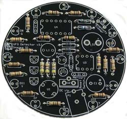
Begin construction by mounting and soldering the 13 - 180 ohm resistors in positions R1 - R12, and R24 (color bands brown, gray, brown, gold). R13 is an 18K ohm 1% resistor (color bands brown, gray, black, red, brown). R14 is a 4.7K ohm resistor (color bands yellow, purple, red). R15 is a 3K ohm 1% resistor (color bands orange, Black, black, brown, brown). The three 470 ohm resistors mount in R17, R18, and R20 ( color bands yellow, purple, brown). The two 1K ohm 1% resistors mount in R19, and R21 (color bands brown, black, black, brown, brown). R22 & R23 are 100K ohm resistors (color bands brown, black, yellow).
Next mount & solder the 8-pin and 14-pin sockets in U3 & U4. The 470uF capacitor should be mounted in C1. The 10uF capacitors are C2 &C3. C4 & C5 are .1uF capacitors.
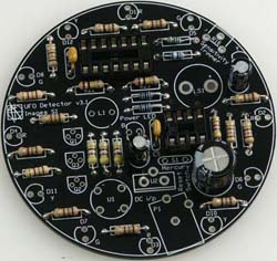
Now mount and solder the three 2N3904 transistors (Q1, Q2 & Q3). The Bridge rectifier should be mounted and soldered in U1. L1 is a 100uH inductor. Mount and solder the speaker (LS1) next. The 7805 voltage regulator is U2. Be sure to orient it to match the printed silkscreen.
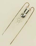
The tilt switch is an important component. It allows you to reset, or turn off, the UFO detector by simply turning it upside down.
The mercury tilt switch is mounted upside down. Bend the leads as shown in the in image to the left and mount and solder in S1. Next mount the 20K potentiometer in R16 and the power jack (P1).
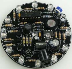
You are now ready to install the 13 LEDs (D1 - D13). Twelve LEDs surround the board with one in the center. The LEDs only pass current in one direction. To orient them correctly, align the shorter lead of the LED to the flat side of the circle printed on the pcb, refer back to Figure 5.