|
Page 2 :Oscillator Circuit Switches Page 3 :Steam Punk Geiger Schematics
|
Page 8 :Assembly Attaching The Lever Switch Page 9 :Building A Steam Punk Wand |
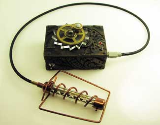
Buy DIY Steampunk Components Here
Build a fully functional Steampunk Geiger Counter.
Geiger counters are instruments that measure nuclear radiation. Our previous online articles already describes the function of Geiger counters, so I will not repeat that information, if you want to view this information go here.
I like the Steampunk movement. Victorian era science has a certain flare to it, especially when its technology exceeds our own technology. While the Steampunk Geiger Counter I am about to describe does not exceed current technology, it's primarily circuit uses Victorian technology. While I couldn't remove all modern semi-conductors from the circuit, I kept them to a minimum and do not use any integrate circuits.
I work with an older Russian engineer who wept when he examined the saw switch circuit I created to generated the high voltage needed to activate the Geiger counter tube. To operate a Geiger counter (GM) tube one requires a high voltage on the order of 400-600 volts. The exact voltage depending upon the particularities of your GM tube. Typically in our present day (non-steam punk) circuits a timer or oscillator circuit is used to control the power to the primary winding (coil) of a step-up transformer to generate the high voltage needed to operate the GM tube.
The oscillator circuit switches the electrical current to the primary winding of the transformer on and off in rapid succession. The inductive high voltage created in the secondary windings of the step-up transformer is fed off the secondary coil for the GM tube.
In keeping with Victorian technology I have eliminated the oscillator circuit and replaced it with a manual saw switch. The manual saw switch also switches the electrical current to the primary winding on and off rapidly, but doing so in a mechanical rather than electronic manner.
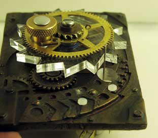
The heart of the saw switch is the saw itself see figure 1. The saw is approximately 3" in diameter. I cut this saw out of 1/4" thick acrylic plastic, see figure 1.
This saw is cut from 1/4" acrylic plastic. A template for the saw is provided at the end of the article. This saw is attached to a board through the center hole and is allowed to rotate freely. A lever switch is positioned to the saw so that when the saw rotates, the teeth on the saw close and open the contacts on the lever switch. This allows us to rotate the saw, which opens and closes the lever switch. Depending upon how fast we rotate the saw determines the speed of the opening and closing of the lever switch. I call the combination of the saw and lever switch, a saw switch.
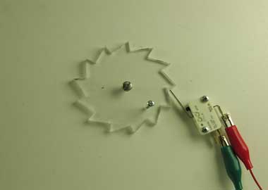
Power to our step-up transformer is controlled (turned on and off) by the saw switch.
Figure 1 is a basic saw switch mounted on a flat board. A small machine screw is placed in a small hole drilled on the saw to act as a handle to rotate the saw by hand. Using this flat model makes it easier to understand how this switch functions. When we fit the saw switch into a case, the lever switch will be mounted under the plastic saw to save space.
However this simple set-up is perfect for learning how the saw switch operates and for testing the Geiger Counter circuit before mounting all the components into its enclosure.
The schematic for our Steampunk Geiger counter is shown in figure 2.
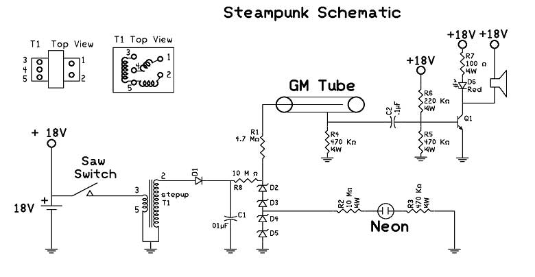
I already explained the saw switch function. We apply 18 volts (from two 9V batteries wired in series) to the primary windings of our step up transformer through the saw switch.
The on-off cycling of power to the transformer creates the inductive high voltage generated in the secondary winding of the transformer that passes through a diode D1 and charges capacitor C1. The zener diodes D2, D3, D4 and D5 regulate the voltage to 450 volts for the GM tube.
When the capacitor is charged, we can siphon off 150 volts from the junction of D3 and D4 to light a neon bulb. The neon bulb indicates when we have a full charge on our capacitor, and optimum power going to our GM tube, at which point the user can stop rotating the saw switch.
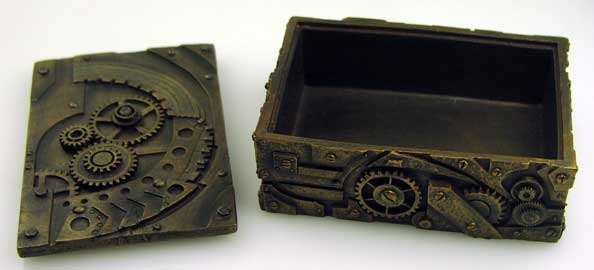
SteamPunk Enclosure
You can build or buy a Steampunk case for your geiger counter. I decided to buy. I found a suitable SteamPunk design box on ebay, see figure 3. The case was a little small, so it made for a tight fit. This enclosure cost $21.99 with free shipping. Search using terms Steampunk box on ebay.
In our Steampunk Geiger counter, the lever switch will be mounted under the acrylic saw, which are both mounted on the case. The acrylic saw must be able to rotate freely. To create a free spinning saw I assembled the following parts: the acrylic saw, a top brass gear(for decoration only), 8-32 machine screw of suitable length, (2)8-32 nuts (not shown), #8 split lock washer (not shown), flat washer (not shown) a brass tube whose inside diameter allows the 8-32 machine screw to pass through and a thrust bearing, see figure 4.
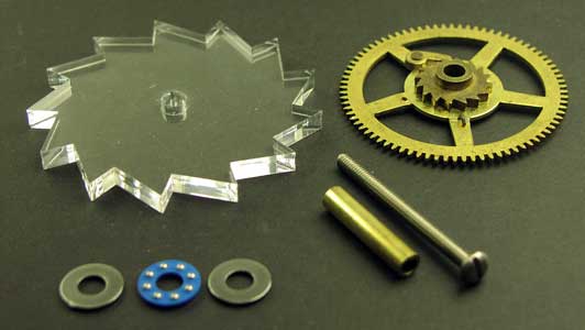
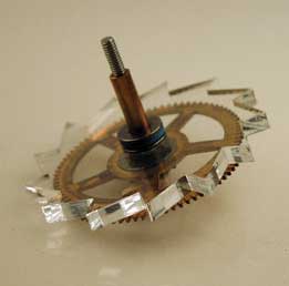
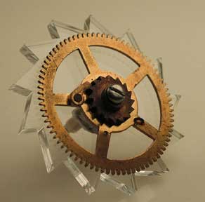
Figures 5 and 6 show how these parts are assembled before installing on case.
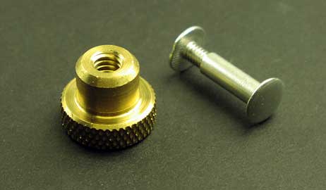
To this we need to add a small brass knob and binding post and screw, see figure 7, to fasten the knob onto the plastic saw to rotate it.
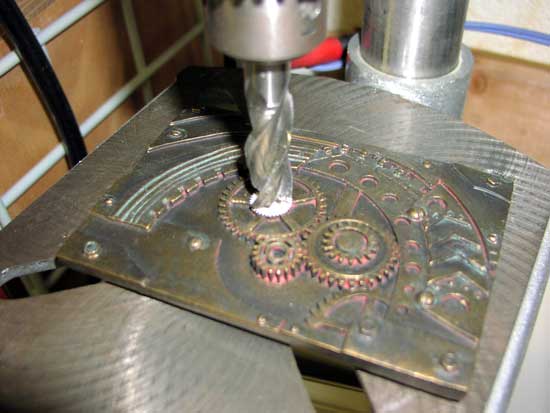
Assembling these parts onto the case is a multi-step process. We first attach the plastic acrylic saw. The box is made of a plastic resin that is easy to machine. Locate a position on your case for the saw switch and drill a hole in the case, see figure 8.
Next place the saw assembly on the case using the hole you just drilled, see figure 9.
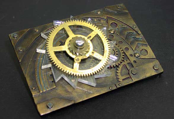
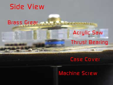
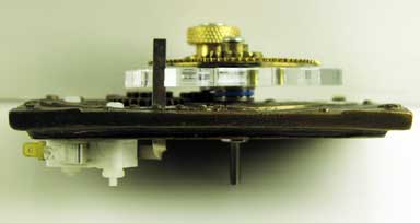
Figure 10 is a side view showing how the components are put together.
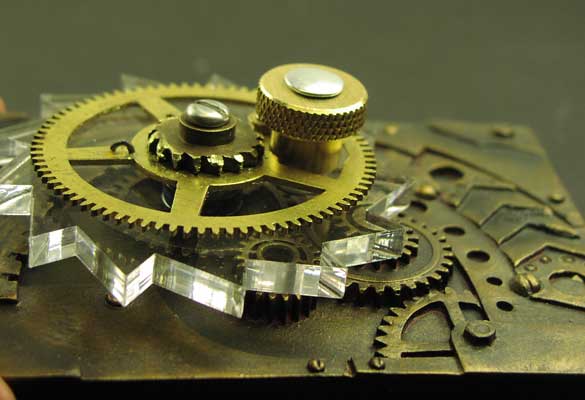
At this point I attached the brass know using a binding post and screw. I positioned the knob between the large space in the decorative brass gear, see figure 11.
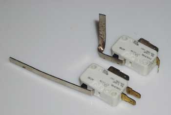
Next we need to locate the hole where we will be putting the lever switch. We are mounting the lever switch on the bottom of the cover, so it is necessary to bend the lever so it will pass up through a hole from the other side of the case cover, see the following figure 12
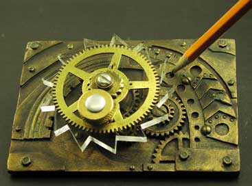
Now that you have an idea of bending the lever on the lever switch we can move to the next step. With the plastic saw positioned on the enclosure locate where the hole should go, see figure 13
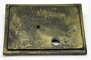
The hole must be in a position that when the lever comes through the hole and the saw is rotated in a clock wise rotation, the lever is hit with the teeth of the saw which in turn the switch on then off with each tooth. The next steps in the fabrication require a little back and forth assembling, testing, measuring, and fabricating. Remove the saw assembly and drill this hole, see figures 14 and 15.

Reattach the saw assembly and dry fit the lever of the lever switch through the hole. You may need to increase the size of the hole to allow clearance for the lever to move enough to switch on and off. When the hole is the right size, position the lever switch so that rotating the saw, turns the switch on and off.
Mark the position of the switch and then drill two holes to mount the switch to the case, see figure 16.
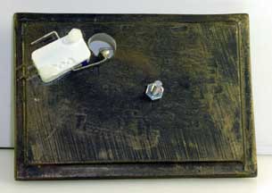
Reassemble the saw on the case alone with the lever switch and check functionality, see figures 17 and 18.
The next item to build is a Steam Punk wand.
I used a SBM-20 Russian Geiger, its stainless steel tube wall looks like copper and fits well with the Steampunk design, see figure 19.
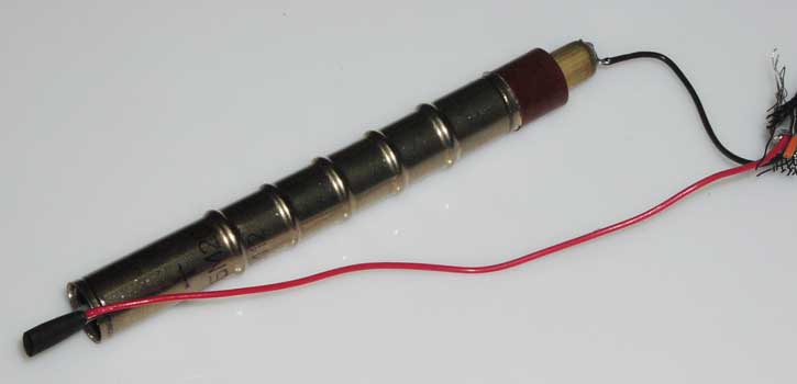
Reassemble the saw on the case alone with the lever switch and check functionality, see figures 17 and 18.The + terminal on the tube is marked on the tube. Before soldering wires onto the terminals you need to determine which kind of wire or cable you will be connecting between the wand and the Geiger counter. I decided to use a three pin mini-cable and panel mounted socket, see figure 20.
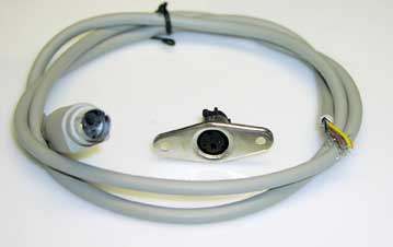
While this is only a three connector cable, there may be 6 wires inside the cable. You need to check which wires are connected to the 3 pin plug. In my cable the red wire was connected to the center pin and the black wire to one pin to the side. I used these wires to supply power to my GM tube. Obtain a panel mounted socket for the connector.
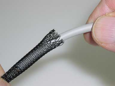
These cables are grey flexible rubber, the gray color being a little too modern for the look I'm looking for. So I covered the cable with a black 3/8" fiberglass mesh before starting fabrication of the wand, see figure 21.
The wand components I used are a 4" plastic tube with the .5" inside and .75" outside diameter. I drilled decorative holes along the side of the tube. Just to add a little interest. Thin 1/8" diameter copper tubing that I bent and fabricated into different shapes. The copper fittings I used have an inside diameter of 3/4" that fits the 3/4" outside diameter of the plastic tube, see fig 22.
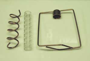
The thin 1/8" copper tubing is easy to bend. I bent one length into a spiral, the other I fabricated to be like hand-hold handles for the wand and soldered it to the top cap.
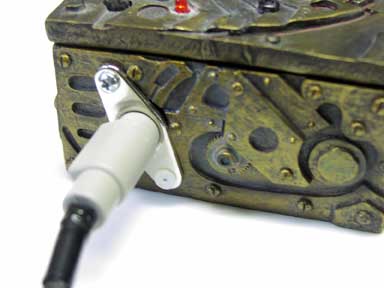
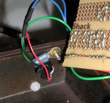
The inside of the panel mounted socket is important. Notice on the outside view I used one metal machine screw and nut to attach socket to case. On the inside photograph, see fig 27, you can see I connected a ground wire from the circuit ground to the socket. This grounds the shield wire and improves performance.
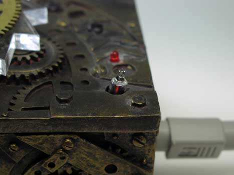
A few more holes are drilled into the case. One for an LED, another for the neon bulb and the last one for a speaker. Space is tight in this case so these holes were drilled. One more hole is drilled into the side for the on-off switch.
Placing the tube into the assembly completes the wand, see figure 25. The copper pieces can be secured with a little glue or epoxy. I used a small amount of silicon to hold the components. The silicon holds everything together just enough. If needed I can disassemble the wand for upgrades or repair.
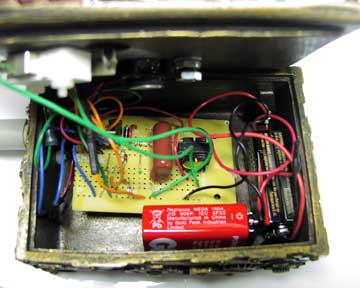
The electronics can be assembled on to a prototyping PCB board. The two 9 volt batteries are aligned across the interior wall, see fig 28.
Operation:
Plug in the Geiger counter wand. Turn of the power from the 9V batteries. The saw switch is rotated at a medium pace for about a minute or so until the NEON bulb lights up, see figure 29. Bring the wand close to a radioactive source. You should see the LED pulse and speaker click every time a radioactive particle is detected.

When the neon light goes out, the detecor will still have enough voltage on the capacitor to power the GM tube, but its not reliable. When not in use remove the 9V batteries.

