
Visual Compass
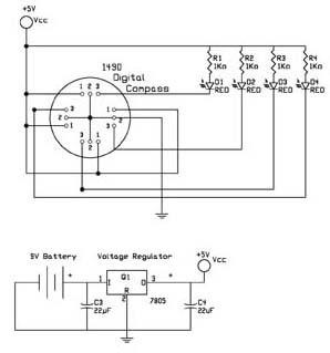
The first test circuit (see figure 5) is about the simplest circuit that can be designed around the device. The sensor is drawn in the schematic as if you are looking through the top of the sensor to the 12 leads below. The circuit uses four LED's for display. Each cardinal position on the compass lights one LED. The intermediate directions light two LED's as shown in figure 6.
Notice that all the number 2 ground leads are tied together. As are the number 1 leads connected to +5 volts Vcc. The sensor will operate supply voltages from 5 to 18 volts. I used a 7805 to regulate the 9V battery to a constant 5 volts. The LED's used in the circuit are red micro-miniature type that operate using little current. The 1K resistors limit the current flowing through the LED's to about 5 mA.
The sensor is dampened to approximate the speed of a liquid filled compass. The dampening prevents over swinging the direction. In addition the built in hysteresis prevents flutter when near a switching direction. The 1490 device is sensitive to tilt. Any tilt greater than 12 degrees will create directional errors.
This circuit may be wired onto our Navigation pc board, see figure 7.
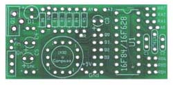
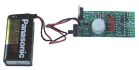
Figure 6, shows the minimum components of figure 5 mounted and soldered to the pc board, figure 7. Q1 is a 7805-voltage regulator. R1 through R4 are 1/8 watt 1K resistors. Four sub-miniature LED's are soldered into the B0 through B4 positions, with the positive lead of the LED orientated on the right side with the board as shown in figure 4. Capacitors C3 and C4 are 22 uF capacitors. 9V battery cap is wired into the Vin positions, and finally a switch is wired on to the pcb in the lower left hand corner.
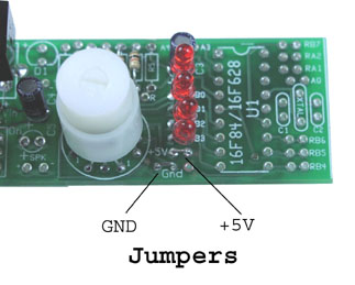
The close up photograph, in figure 8, shows two jumpers that need to be soldered in, that supply power and ground to the 1490 compass.
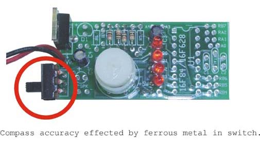
When I first assembled this circuit onto the board it did not function properly. The compass did not respond, as it should. I tracked the problem to the switch that is in close proximity to the compass see figure 9. The switch casing is made of a ferrous material that was disrupting the compass function. When I removed the switch and replaced it with another without any ferrous metal, the circuit responded properly.
Testing & Calibration
To calibrate the compass you will need to use a standard magnetic compass. Find north with the standard compass. Rotate the prototype assembly so that just one LED is lit. Use that lit LED as north. If the wiring of the sensor matches the schematic the other 3 arrays will automatically fall in proper sequence. I used the LED furthest away from the sensor for north. The digital compass does not have a definitive magnetic north reading (position). You can make magnetic north any one of the LED readings shown below. Turning the compass in a clockwise direction will cause the LEDs to light, following the sequence shown in the table 1. In the table I chose North to be 0001, but you may make North any one of the lighted sequences, and start from there.
The sequence for my array follows: 1 = on, 0 = off.
| |
|
|
|
| |
|||
| |
|
|
|
|
|
|
|
|
|
|
|
|
|
|
|
|
|
|
|
|
|
|
|
|
|
|
|